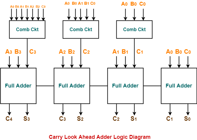
Look Ahead Carry Generator Circuit Diagram. Download Look Ahead Carry Generator Circuit Diagram PNGCarry input and output of the alus are. It requires 1 and gate and 1 or gate. The Carry Look-Ahead CLA logic block which consists of four 2-level. Four sets of P G logic each consists of an XOR gate and an AND gate.

The 4-bit Carry Look Ahead adder block diagram is shown in Fig4. Carry Generator The carry generator in the CLA takes as its inputs the propagategenerate signals and generates a carry. Instead of using n 1-bit carry lookahead cells. The time complexity of carry look ahead adder Θ logn. The carry propagate Pi and carry generate Gi variables are shown on the full adder logic circuit. Carry Look Ahead Adder Circuit Diagram Posted by Margaret Byrd Posted on December 16 2020 4 bit carry look ahead adder circuit lookahead in vhdl and code 8.
The part that adds the input bits and the carry for each bit position.
Si Sum and Ci1 Carry out for the next stage are the outputs for the next stage of the adder. Carry Generator The carry generator in the CLA takes as its inputs the propagategenerate signals and generates a carry. The carries C1 C2 and C3 can be expressed in SOP form as functions of C0 and the different Pi and Gi as follows. Carry Look Ahead Adder Circuit Diagram Posted by Margaret Byrd Posted on December 16 2020 4 bit carry look ahead adder circuit lookahead in vhdl and code 8. 4 bit carry look ahead adder circuit lookahead in vhdl and code 8. It generates the carry-in of each full adder simultaneously without causing any delay.