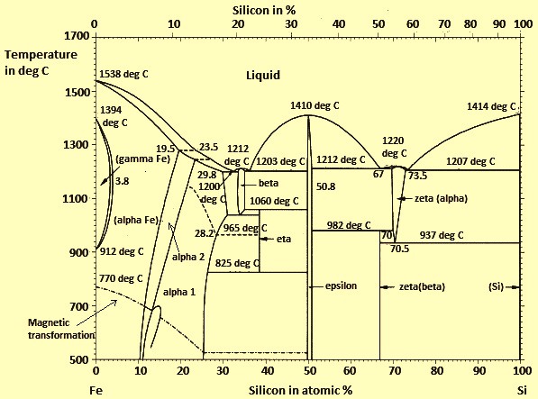
Iron Silicon Phase Diagram. Part 1 ASM International Metals Park OH 3142 1987. Raghavan The Cr-Fe-Si SystemPhase Diagrams of Ternary Iron Alloys. Manganese-iron-silicon The ternary system manganese-iron-siliconis shown in figure 9 and 10. A map of the temperature at which different phase changes occur on very slow heating and cooling in relation to Carbon is called Iron- Carbon Diagram.

Microstructures observed on eutectic and eutectoid phase diagram for different composition values are explained. There is no need to point out the importance of assessed phase diagrams to metallurgists or even anyone concerned with the technology and applica tion of metals and alloys. This phase diagram can be used for the analysis of the phase composition of an 8001 alloy Table 71 that contains only nickel and iron as the alloying elements. Thus the terminal solid solutions are nearly pure Al and Si under equilibrium conditions. The liquidus surface is divided at 50 a Si by the continuous ridge ofMnFeSi. Solidus line separates solid region from liquid solid region below this line only solid solution is present.
318 illustrates this diagram and photomicrographs of alloys at room temperature.
The liquidus surface is divided at 50 a Si by the continuous ridge ofMnFeSi. Solid liquid α L 3. This diagram is also the basic diagram for casting alloys of the 5120 type that are considered in Chapter 4. As the silicon content of the alloy increases the amount of iron that can be tolerated before the E-phase starts to form prior to the Al-Si eutectic increases. The Al-Si Phase Diagram The binary Al-Si phase diagram was initially studied by Fraenkel of Germany in 1908. Thus the terminal solid solutions are nearly pure Al and Si under equilibrium conditions.