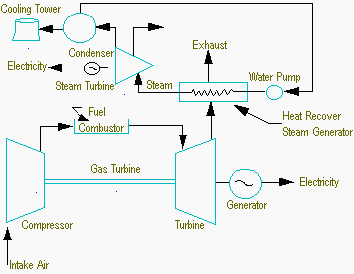
Combined Cycle Power Plant Block Diagram. Figure 44 A block diagram of a combined cycle power plant passes through it horizontally and the watersteam pipes which collect the heat are hung vertically in its path. This combined cycle power plant has the main parts like compressor combustor turbine alternator generators condenser boiler feed pump and the Heat Recovery Steam Generator HRSG. Simplified block diagrams of these configurations are presented in Figure 1. A combined cycle power plant or combined cycle gas turbine CCGT uses both a gas turbine and a steam turbine together to produce more electricity from the same fuel than a traditional simple cycle power plant.

Create Power Plant Diagram examples like this template called Power Plant Cycle Diagram that you can easily edit and customize in. Learn whether pressure or temperature switches can be used in gas or steam turbines for combined cycle power plants with power plant system schematic. A heat recovery steam generator HRSG is an energy recovery heat exchanger that recovers heat from a hot gas stream such as a combustion turbine or other waste gas stream. In this combined cycle NG is the fuel that is fed to the combustion chamber. The single-shaft STAG system con- sists of one gas turbine one steam turbine one generator and one HRSG with the gas turbine and steam turbine coupled to the single gener- ator in a tandem arrangement on a single shaft. Block flow diagram BFD for the CCGT plant in Aspen HYSYS.
And solar energy power plants and are subjected to daily start up peaking operation and load following to smooth out fluctuations in renewable solar and wind generation.
Todays advanced combined cycle. The GT is used to expand the high-pressure exhausts to produce power. A Gas turbine GT b-c Steam cycle SC. In this combined cycle NG is the fuel that is fed to the combustion chamber. It produces steam that can be used in a process cogeneration or used to drive a steam turbine combined cycle. The vertical HRSG reverses these arrangements.