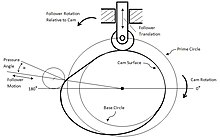
Cam And Follower Diagram. Check the schematic representation of the Cylindrical cam with both the reciprocating follower and the oscillating follower. These are as follow. The cam continues to rotate and the follower begins to rise in diagrams 5 and 6 until it returns to its original position. Displacement DiagramA displacement diagram is a graph showing displacement of the follower plotted as a function of timeDegrees of cam rotation are plotted along the horizontal axis and the length of the diagram represents one revolution of thecamSince the cam speed in rpm is constant equal angular division also represent equal time incrementsDisplacement of the follower is plotted along the vertical axis.

We can say that the cam and followers are the most important part of the mechanisms. Point of fictitious knife-edge follower. Cam Terminology and Displacement Diagram. Displacement diagram of a follower. We assume that the cam mechanism will be used to realize the displacement relationship between the rotation of the cam and the translation of the follower. 120-210 follower rises 21 mm with uniform retardation.
120-210 follower rises 21 mm with uniform retardation.
Its displacement can be plotted against the angular displacement θ of the cam and it is called as the displacement diagram. In diagram 1 the cam is in a vertical position and it slow rotates in an anticlockwise direction. It is the curve drawn. It is widely used in automobile industries to direct opening and closing of inlet and exhaust valves at desire time. Cam and follower is a type of assembly both works together in any machine element. These are as follow.