Buck Boost Converter Design. There are two basic topologies in DC-DC converters that are isolated and non-isolated DC converters. Tech in Electrical Engineering By Abhishek Pal 11701614002 Soumak Dutta 11701614047 Ankur Bose 11701614009 Under the supervision of Mr. De Automação e Sistemas Universidade Federal de Santa Catarina 88040-900 Florianópolis SC Brazil Depto. Pomar Garcia mpogardasufscbr Gloria Gutierrez gloriaautomuvaes Julio E.

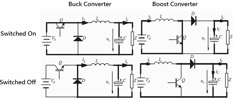
Series resistance of capacitor rC. To work in todays technical environment we have to deal with a rapidly changing market of electronic products and components. The short and direct method is to convert DC-DC directly using Boost converter or buck converter. It also has a similar arrangement as a buck converter circuit consisting of a diode and an energy storage element but it is slightly different. The second switch used is a diode. It is widely used throughout the industry to convert a higher input voltage into a lower output voltage.
The converter operates as a buck-boost converter where all the four switching are switching.
This video introduces. Martin Ordonez and instructor Ignacio Galiano Zurbriggen in a lesson on the design and analysis of the buck-boost converter. Inverting buck-boost converter Figure 1 shows the schematic of a basic inverting buck-boost converter along with the typical voltage and current waveforms in continuous conduction mode CCM. O o V D V RCf The effect of parasitic elements in dc-dc converter The parasitic elements in a dc-dc converter are due to the losses associated with the inductor capacitor switch and diode. Tech in Electrical Engineering By Abhishek Pal 11701614002 Soumak Dutta 11701614047 Ankur Bose 11701614009 Under the supervision of Mr. The non-ideal characteristic of parasitic elements are.